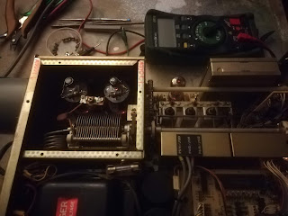
Old rigs of s.k. Eltje PA3CEE here for check and repair
The rig's looked like they have been working in a brown cafe for years
He was a real smoker ...
 |
| the "tank" FT902DM very heavy rig |
 |
| permeability tuning very well build equipment. Plug-in modules. |
The 100pf 1000V mica capacitor was shorted and caused the 6146 damage one tube glas was busted
I replaced both tubes ... warning be very careful not to touch the anode part almost 1000V stays long time loaded in the HV high capacity capacitors, no bleeder R it seems.
Before doing any work make sure the anode C is unloaded I used a 10k resistor against ground with an isolated gripper and grounded wire!
----------------- the other rig 144 - 146 MHz all mode --------------------------------
 |
| FT225RD 20-25W rf |
The original front end was replaced by a Mutek front as that was often done 30 year ago.
However my FT221R the preceding have the original front-end ,i can't find this one less performing. And the FT221 can handle the extreme strong local contest station PA1T . That is about the strongest signal on the band.
It is not like in the glory days of 144MHz activity 30years ago when this FT225 was state of the art.
The FT221R is taking very low standby power less then 300mA at 13.5V Not using the internal power supply since that is getting very hot in long FM QSO
Unfortunate The FT221 / 225 have no PC interface it is also not stable enough for WSPR / FT8 modes.
One FT225/215 issue is bad contact in the switches. It was hard to switch modes in this FT225 loud cracking in the speaker but simply a few drops of ordinary spiritus upon the outside of the switches completely smooth and quiet now.
My IC706 that is not much younger but still technically up to date
Receiving 144MHz cw /usb signals is a pleasure on the old rigs with almost zero ground noise . Most SDR rigs bring among a lot of extras also a high internal noise level.
No matter how well the DSP filters function this noise wil stay.
No CTCSS sub carrier for repeater option but it has a Tone burst unit that generates 1750Hz
when pressing burst button , that will not work for repeaters using CTCSS lock
I use a small pcb based upon Attiny85 that can generate 4 selectable designed by PE1JVU
His software uses Pwm output this makes a reasonable clean sinus signal with a simple RC filter
An other CTCSS using a pic controller i use outputs a square wave difficult to make a sinus shape with a simple RC filter and therefore have hum overtone issues
 |
| the Attiny is programmed with the bin file using Ponyprog, i had an issue when setting the fuses CLK3-0 1111 as noted in the program source the Attiny was "bricked" Needed the reset the fuses to default with an rescue Uno sending 12V "highvoltage" pulses to the Attiny reset. https://sites.google.com/site/wayneholder/attiny-fuse-reset |
-------------------------------------------------------
Last weekend was the May IARU VHF/UHF contest.
Everything is completely different in the Corona virus lock down
So PI4GN multy band/operator operation was no possible! who could imagine this in the last March contest!
Now i should do the 23cm part from home
My modest 23cm is a 1.2m dish with transverter direct on it 35W out
Rx the latest SKY67150 LNA 0.4 n.f measured claimed 0.3 n.f. bandpass filter included.
What to expect when most big contest clubs are forced QRT and tropo is very poor
more home stations i hoped for..
Saturday morning i had to replace a control cable connector due in-watering
But the 23 band was empty very quiet the normal in-range beacons all very weak .
It was was hard to find QSO partners a QSO was rare..
Only Airplane scatter could be used .
Installed latest Airscout version the old one showed no planes.
Then Sunday 4 hours before end sudden no more RF power
something wrong receiving was still okay
Premature end of this remarkable weird contest forced with only 22 contacts
worst ever March was also poor tropo but then our club station was operating and others in EU
70cm could bring 23 skeds
then we had 65 Q average over 400km .
things can change quick


Comments