14-4-2018 updated

Above the low noise preamp 50 - 4GHz ebay 6€
Tested 2 small porto antennas
1 Baofeng UV antenna left 2nd best signal on PI2NOS
2 eBay DIAMONDSRH805S wide band 144/432/1200 it works for its size as expected
3 piece of wire : best signal in the setup...
Unit under test at workbench.
It was stable 50mA at 5V few days, but sudden the current went up to 100mA
And i could no longer adjust it with the negative bias Voltage.
The - Voltage went to zero and the SPF input port became low Z.
This SPF5189z was broken no oscillations, no input overload just it broke while i was receiving the PI2NOS 430.125 using a small antenna at the workbench.
The specs of SPF5189z say it has an internal circuit regulating the bias current.
Replaced . again with an other of the 5 spare SPF i have.
The new one again could be adjusted at 50mA 5V
The current raises to 150mA when removing the negative gate voltage.
Where is that internal bias circuit ?
I suspect eBay SPF5189z devices like al other eBay semiconductors..
But the pre-amp is working good
Reception of the RTL2832u USB receiver is improved a lot with this preamp
This year tested the shielded version SPF5189 at 2018 Heelweg microwave meeting
result: 0.73dB nf @ 23cm 0.45dB nf @70cm out of the box!
But the un shielded version pre-amp above drawed right from the start very high current at 5V
over 200mA way more then the specified 90mA
Thought my SPF5189z must be wrong so i replaced it
But with the other SPF5189z same very high current practical short circuit
it could not run at 5V
Reduced to 3V with 3x Si diodes and a 1 OHm serial resistor.
current still about 100mA . This way it was running months with good result.
Enough through-gain to get over 30m RG58 -6dB at i.f. 146MHz
Daily copy 5 Beacons GB3MHZ OZ7IGY ON0TB DB0VC DB0XY PI7ALK
But started some issue with bad joints in the SMA to N connections
Added SWR bridge to monitor the TX down in the shack.
Placed a new SPF5189z preamp, a type with metal shield drawing correct 90 -100mA at 5V
Al seemed okay but 23cm had cracking noise in some directions like never ending thunderstorm QRM And also the usual S5 noise level at 146MHz was only S1 in low QRM directions
QRM at 23cm a new experience could it be nearby high GSM signals 4G
I will have to mak my own QRM hunting device
Agentschap Telecom was here to investigate my reported QRM problems
Still unsolved Solar Edge noise and digi 200kHz apart carriers.
But AT could not see noise raise on their portable spectrum analyser using special band antenna's
I have S5 noise raise at 50MHz with a 2 ele directed to the Solar panels 50m North of me
the digi trash carriers peak S9 + at 6m 50.198
Repeating every 200kHz in the whole 1MHz to 150MHz band SolarEdge works as a broadband QRM transmitter !
The source is in the CPU part of the controller that i found out with the IC706 at 50.198MHz and a short pick up wire
Close to the SOLAR EDGE, the digi carrier trash clearly was strongest near the Solar Edge display not on the PV cables
Those cables need to be twisted i got an PV cable powerline filter from SolarEdge but since the RFI comes from the internal CPU the filters did not help
Digi thrash cariers with maximum of 9+20 at 14.198 MHz on a dipole repeated every 200kHz. up to VHF !
Frustrating that QRM like this is legal and malfunctioning Solar devices can operate like this.
A ham would think just build TX and skip the LP-filters..
My own Solar Frontier SAF3600 system is absolute RF quiet.
To continue with the SPF5189z pre-amp
No signs of self oscillating. Matching to the 23cm slot dipole SWR 1:1.
The antenna relay okay, so what else could it be then the pre-amp became bad?
Still receive Beacons much weaker then usual.
I had 5 spare SPF5189z replaced the SPF same high current at 5V
The Device specification says 5V 90mA .
Diode testing, the input shows 0.6V barrier and reverse 1.4V
The output is just 0 Ohm's both way's all 5 devices
Then with a second diodetester reverse on the input with a small negative Voltage
The output Z went up from zero to a high value !
As if this SPF5189z would need a negative input bias Voltage.
So i made a smal negative voltage source adjustable and through a small choke coil applied it to the input gate of the SPF5189z and voila smoothly the Supply current is adjusted to the wanted value.
Regulating -1V 40mA to -0.65V is 90mA
next question is the preamp stil working
A simple test showed that it does amplify I can let it self oscillate by touching the input wit a pincet
The RF detector at the output goes high.
Does it stil have low noise i do not know. Soldering de-soldering needs high soldering power due to the big grounding pad
There is no soldering instruction in the specs but it must be the same rules as for most chips
Next thing is making a small adjustable negative bias supply and modifying the preamp with a -bias connection a bit
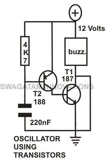
A negative Voltage supply with the NE555 or 2 transistors 1kHz AC oscillator both work okay.
But the whole thing became a bit more complicated.
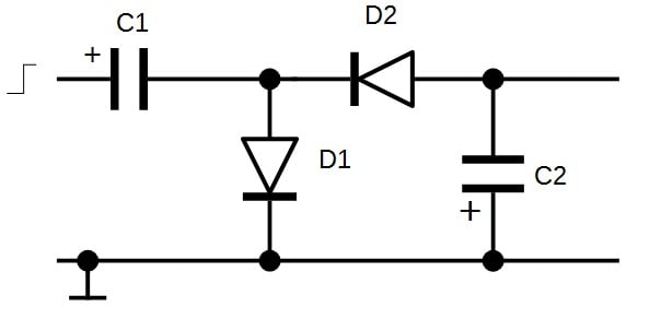
Negative Voltage generating example here
https://www.allaboutcircuits.com/projects/build-your-own-negative-voltage-generator/
About 1 kHz AC generator with a 2 diode rectifier below will make nearly -5V with +5Vsupply
diodes IN60 r 100nF give about 1kHz the buzz. replaced with 500R
The collector output is connected to the negative rectifier circuit below.
<3v ...="" p="">
<3v ...="" p="">
<3v ...="" p="">So my SPF5189z need negative bias and i am the only Ham experiencing this?
Hard to believe but no Google hits on the subject
40mA adjusted
 90mA at - 0.64V bias


Above the low noise preamp 50 - 4GHz ebay 6€
Tested 2 small porto antennas
1 Baofeng UV antenna left 2nd best signal on PI2NOS
2 eBay DIAMONDSRH805S wide band 144/432/1200 it works for its size as expected
3 piece of wire : best signal in the setup...
Unit under test at workbench.
It was stable 50mA at 5V few days, but sudden the current went up to 100mA
And i could no longer adjust it with the negative bias Voltage.
The - Voltage went to zero and the SPF input port became low Z.
This SPF5189z was broken no oscillations, no input overload just it broke while i was receiving the PI2NOS 430.125 using a small antenna at the workbench.
The specs of SPF5189z say it has an internal circuit regulating the bias current.
Replaced . again with an other of the 5 spare SPF i have.
The new one again could be adjusted at 50mA 5V
The current raises to 150mA when removing the negative gate voltage.
Where is that internal bias circuit ?
I suspect eBay SPF5189z devices like al other eBay semiconductors..
But the pre-amp is working good
Reception of the RTL2832u USB receiver is improved a lot with this preamp
This year tested the shielded version SPF5189 at 2018 Heelweg microwave meeting
result: 0.73dB nf @ 23cm 0.45dB nf @70cm out of the box!
But the un shielded version pre-amp above drawed right from the start very high current at 5V
over 200mA way more then the specified 90mA
Thought my SPF5189z must be wrong so i replaced it
But with the other SPF5189z same very high current practical short circuit
it could not run at 5V
Reduced to 3V with 3x Si diodes and a 1 OHm serial resistor.
current still about 100mA . This way it was running months with good result.
Enough through-gain to get over 30m RG58 -6dB at i.f. 146MHz
Daily copy 5 Beacons GB3MHZ OZ7IGY ON0TB DB0VC DB0XY PI7ALK
But started some issue with bad joints in the SMA to N connections
Added SWR bridge to monitor the TX down in the shack.
Placed a new SPF5189z preamp, a type with metal shield drawing correct 90 -100mA at 5V
Al seemed okay but 23cm had cracking noise in some directions like never ending thunderstorm QRM And also the usual S5 noise level at 146MHz was only S1 in low QRM directions
QRM at 23cm a new experience could it be nearby high GSM signals 4G
I will have to mak my own QRM hunting device
Agentschap Telecom was here to investigate my reported QRM problems
Still unsolved Solar Edge noise and digi 200kHz apart carriers.
But AT could not see noise raise on their portable spectrum analyser using special band antenna's
I have S5 noise raise at 50MHz with a 2 ele directed to the Solar panels 50m North of me
the digi trash carriers peak S9 + at 6m 50.198
Repeating every 200kHz in the whole 1MHz to 150MHz band SolarEdge works as a broadband QRM transmitter !
The source is in the CPU part of the controller that i found out with the IC706 at 50.198MHz and a short pick up wire
Close to the SOLAR EDGE, the digi carrier trash clearly was strongest near the Solar Edge display not on the PV cables
Those cables need to be twisted i got an PV cable powerline filter from SolarEdge but since the RFI comes from the internal CPU the filters did not help
Digi thrash cariers with maximum of 9+20 at 14.198 MHz on a dipole repeated every 200kHz. up to VHF !
Frustrating that QRM like this is legal and malfunctioning Solar devices can operate like this.
A ham would think just build TX and skip the LP-filters..
My own Solar Frontier SAF3600 system is absolute RF quiet.
To continue with the SPF5189z pre-amp
No signs of self oscillating. Matching to the 23cm slot dipole SWR 1:1.
The antenna relay okay, so what else could it be then the pre-amp became bad?
Still receive Beacons much weaker then usual.
I had 5 spare SPF5189z replaced the SPF same high current at 5V
The Device specification says 5V 90mA .
Diode testing, the input shows 0.6V barrier and reverse 1.4V
The output is just 0 Ohm's both way's all 5 devices
Then with a second diodetester reverse on the input with a small negative Voltage
The output Z went up from zero to a high value !
As if this SPF5189z would need a negative input bias Voltage.
So i made a smal negative voltage source adjustable and through a small choke coil applied it to the input gate of the SPF5189z and voila smoothly the Supply current is adjusted to the wanted value.
Regulating -1V 40mA to -0.65V is 90mA
next question is the preamp stil working
A simple test showed that it does amplify I can let it self oscillate by touching the input wit a pincet
The RF detector at the output goes high.
Does it stil have low noise i do not know. Soldering de-soldering needs high soldering power due to the big grounding pad
There is no soldering instruction in the specs but it must be the same rules as for most chips
Next thing is making a small adjustable negative bias supply and modifying the preamp with a -bias connection a bit
A negative Voltage supply with the NE555 or 2 transistors 1kHz AC oscillator both work okay.
But the whole thing became a bit more complicated.
Negative Voltage generating example here
https://www.allaboutcircuits.com/projects/build-your-own-negative-voltage-generator/
About 1 kHz AC generator with a 2 diode rectifier below will make nearly -5V with +5Vsupply
diodes IN60 r 100nF give about 1kHz the buzz. replaced with 500R
The collector output is connected to the negative rectifier circuit below.
<3v ...="" p="">
<3v ...="" p="">
<3v ...="" p="">So my SPF5189z need negative bias and i am the only Ham experiencing this?
Hard to believe but no Google hits on the subject
40mA adjusted


Comments
Recommend power supply by Mini Buck Converter that does have smd chip marked AGCG.
It will step down from any 5V or higher source.
It confirms my suspicion of this devices from China
It confirms my suspicion of this devices from China
Let me suggest another method to force the amplifier to behave properly.
Cut the ground plane of Minus connector, or provide separate board for supply connecting. Insert in Minus line toward ground a parallel of: 10R 10R 100n. Voltage drop on (smd) resistors will be -0.5V, power neglectable. Connect the input pin of amplifier as you did, through small inductor to -0.5V. Mind the 100pF immediately after the inductor to ground.
There are measuring results, total voltage, device will get U-0.5:
U 3.0 4.0 5.0
I 100 106 111 mA
for minus you can use ICL7660.
this system immediately provides a negative voltage and its value can be determined using a resistor divider.
https://drive.google.com/file/d/1J4wcA4miH3nqLNvtonE-H4zK33cQzb2t/view?usp=share_link
Należy dobrać R25 aby uzyskać 0,65V -:)
https://drive.google.com/file/d/1WlmdtQ0GqFqKjMYZyhLyUcUR-T_hYM8N/view?usp=sharing